
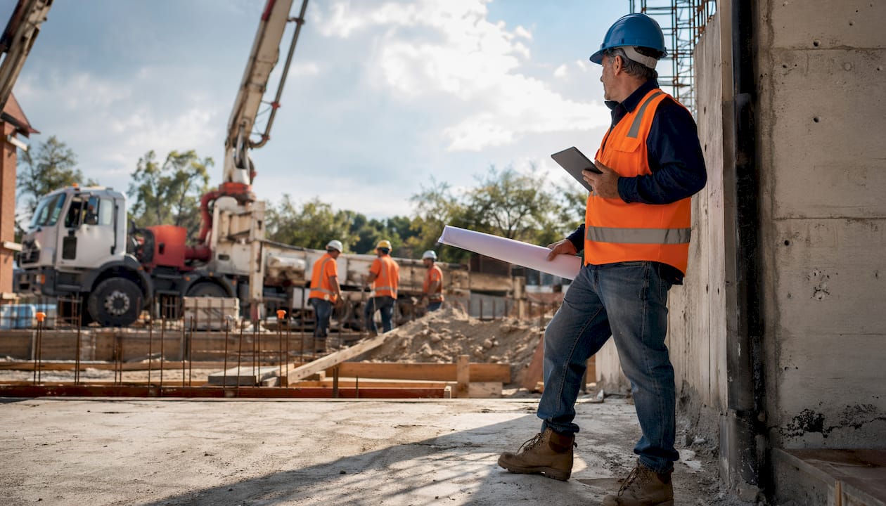
A concrete placement plan is defined as a formal technical document that specifies pour sequence, joint locations, delivery temperature, ambient conditions, and consolidation methods for a concrete pour. Any single placement exceeding 50 cubic yards requires this document as a mandatory submittal before work begins. That threshold covers most commercial slabs, elevated decks, and structural walls. Without a written plan, crews make decisions on the fly, and those decisions rarely hold up under pressure.
A concrete placement strategy is not just paperwork. It is the coordination tool that keeps your pump operator, finishing crew, and ready-mix supplier working from the same script. Builders who skip this step routinely face cold joints, honeycombing, and costly remediation. This guide breaks down every component of an effective plan and shows you how to execute it without defects.
What is a concrete placement plan and why does it matter?
A concrete placement plan is the technical blueprint that governs how concrete moves from the truck to its final position in a structure. It covers pour sequence, layer thickness, vibration methods, joint placement, and environmental controls. The document exists to eliminate guesswork before the pour begins, not during it.
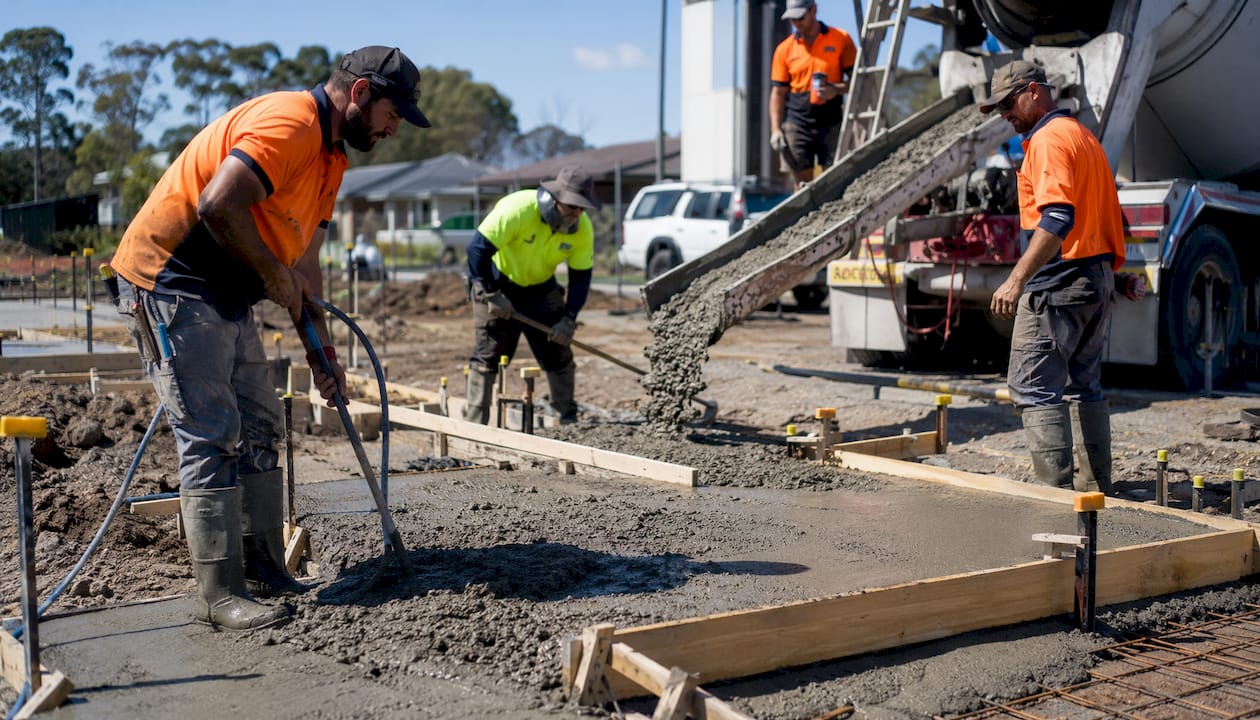
The plan matters because concrete has a fixed working window. Industry standards set a 90-minute discharge window from batching to final discharge, with some specialized mixes requiring placement within 40 minutes after adding superplasticizers. Miss that window and the material stiffens in the form. The cost is not just wasted concrete. It is structural compromise.
Builders who treat the placement plan as a formality tend to learn its value the hard way. A cold joint in a retaining wall or a honeycomb void in a column base can trigger engineer hold-points, demolition orders, and insurance claims. The plan prevents all of that by assigning responsibility and timing to every step of the pour.
The importance of concrete placement planning also extends to legal compliance. A building permit for concrete work in Melbourne typically requires a placement plan as part of the documentation package for structural elements. Submitting without one delays approval and signals poor project management to the certifier.
What are the essential components of a concrete placement plan?
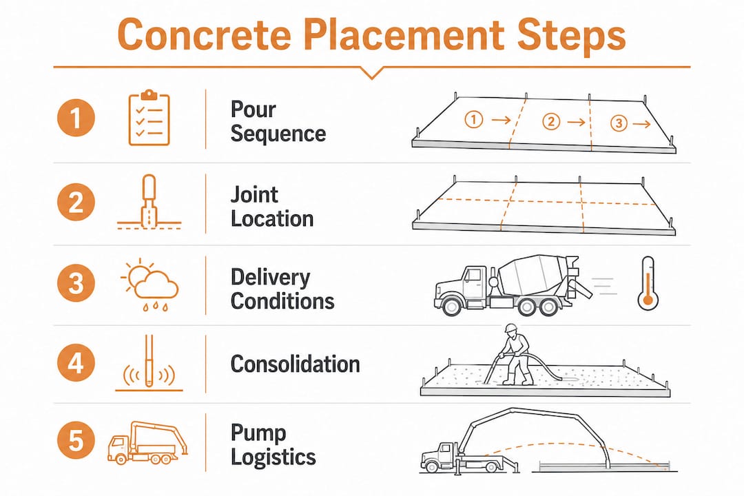
Every placement plan must address four core areas: pour sequencing, joint location, delivery conditions, and consolidation methods. Missing any one of them creates a gap that shows up as a defect in the finished structure.
Pour sequencing
Pour sequencing organizes the concrete placement into controlled sections or layers. Large slabs are divided into bays, and each bay is poured in a defined order to manage shrinkage and thermal gradients. Sequencing also determines which areas receive concrete first so the finishing crew can work without being trapped behind fresh material.
Joint location planning
Construction joints must be located at low-stress areas with proper surface roughening and waterstops installed to prevent structural issues and leaks. Contraction joints are cut or formed at regular intervals to control where shrinkage cracks occur. Placing joints in the wrong location transfers stress to unreinforced sections and creates future maintenance problems.
Delivery conditions
The plan must specify the concrete temperature at delivery, the ambient temperature range, and the maximum time from batching to placement. Hot weather and cold weather each require different mix adjustments and site preparations. Ambient temperature and humidity directly impact setting time and must be integrated into the plan with contingencies for unexpected weather changes.
Consolidation details
Vibration is the primary consolidation method for cast-in-place concrete. The plan must specify vibrator type, insertion spacing, insertion depth, and the number of operators assigned. Under-vibration leaves voids. Over-vibration causes segregation. Both produce defects that are expensive to repair after stripping.
- Pour sequence mapped to bay layout and finishing crew position
- Joint locations marked on formwork drawings with waterstop specifications
- Delivery temperature range and maximum truck wait time defined
- Vibrator insertion pattern, spacing, and operator assignments documented
- Contingency protocols for rain, extreme heat, or truck delays
Pro Tip: Attach a one-page pour sequence diagram to the placement plan. Crew members who do not read dense technical documents will follow a clear visual map.
How do you plan concrete delivery and pump logistics?
Pump and delivery logistics are where most placement plans fall short. Scheduling trucks with appropriate intervals prevents both cold joints from gaps and congestion from bunching. The goal is a steady, uninterrupted flow of concrete from the plant to the form.
Effective pump positioning balances reach, truck traffic flow, and site logistics to prevent pipeline blockages and maintain concrete quality. A pump placed too far from the pour face increases pipeline length, raises pressure requirements, and slows the pour rate. A pump placed too close to the site entrance blocks truck access and creates dangerous congestion.
- Map the pour face first. Identify the farthest point from the pump and confirm the boom or pipeline can reach it without repositioning mid-pour.
- Schedule truck intervals. Space deliveries to match your pour rate. A gap of more than 20 minutes in a large pour risks the surface stiffening before the next load arrives.
- Sequence from far to near. Pouring from the farthest point back to the pump keeps fresh concrete landing on fresh concrete and shortens the active pipeline as the pour progresses.
- Define washout areas upfront. Planned washout locations prevent site contamination and keep trucks moving without disrupting the pour schedule.
- Confirm access routes. Mark entry and exit paths for trucks so drivers do not improvise. Improvised routes damage formwork, underground services, and neighboring work.
Pro Tip: Walk the pump position and truck route the day before the pour. Problems that look fine on paper become obvious on site.
For larger projects, the role of concrete pumping in sequencing decisions deserves its own section in the placement plan. Boom pump reach, line pump pipeline routing, and truck staging areas each affect pour speed and quality in ways that cannot be improvised on pour day.
Best practices for concrete placement execution and compaction
Placement execution is where planning meets physical reality. The best practices for concrete placement center on layer control, drop height, vibration discipline, and environmental monitoring.
Concrete should be placed in horizontal layers no thicker than 300–500 mm, and free-fall height should not exceed 1.5 meters to prevent segregation. Thicker layers trap air and prevent vibrators from reaching the bottom of the lift. Excessive drop height causes the coarse aggregate to separate from the paste, producing a weak, porous matrix.
| Parameter | Recommended limit | Risk if exceeded |
|---|---|---|
| Layer thickness | 300–500 mm | Incomplete compaction, voids |
| Free-fall height | 1.5 m maximum | Aggregate segregation |
| Vibrator insertion spacing | 1.5× vibrator radius | Unconsolidated zones |
| Discharge window | 90 minutes from batching | Stiffening, cold joints |
Vibration requires a defined insertion pattern, not random probing. Operators insert the vibrator vertically, withdraw it slowly at roughly 75–100 mm per second, and move to the next insertion point at a spacing no greater than 1.5 times the vibrator’s effective radius. Each insertion should penetrate the previous layer by at least 150 mm to knit the lifts together.
- Place concrete as close to its final position as possible. Do not use vibrators to move concrete horizontally.
- Assign one vibrator operator per active pour face to maintain continuous consolidation.
- Monitor air temperature and concrete temperature throughout the pour. Adjust curing protocols if conditions shift outside the plan’s defined range.
- In hot weather, shade the forms, pre-wet the subgrade, and begin curing immediately after finishing. In cold weather, use wet weather and temperature controls to protect the fresh concrete from early freezing.
What are the common pitfalls in concrete placement planning?
Most placement failures trace back to four recurring mistakes. Recognizing them before the pour is far cheaper than fixing them after.
Delays that consume the discharge window. A ready-mix truck arriving at an unprepared site wastes the 90-minute discharge window and risks cold joints and concrete stiffening. The fix is simple: the site must be ready before the first truck is called, not when it arrives.
Poor site preparation causing truck bottlenecks. Narrow access routes, unmarked staging areas, and blocked pump positions force trucks to wait with drums turning. Every minute of waiting consumes the discharge window and increases the risk of a rejected load.
Ignoring weather impacts. Cold weather requires heated enclosures and hot water in the mix, while hot weather demands faster placements and protective curing measures. Builders who write a placement plan in mild conditions and then ignore a forecast change on pour day create the exact problem the plan was designed to prevent.
Poor coordination between vibration and finishing crews. When finishing crews advance ahead of vibration, they seal the surface before air can escape. The result is surface blistering, delamination, and in wall pours, honeycombing behind the form face.
A concrete placement plan only works if every crew member on site has read it, understood it, and signed off on their role before the first truck arrives. A document sitting in the site office does nothing for the crew at the pour face.
Key Takeaways
A concrete placement plan is the single most effective tool for preventing structural defects, schedule overruns, and costly remediation on any pour exceeding 50 cubic yards.
| Point | Details |
|---|---|
| Mandatory threshold | Any pour exceeding 50 cubic yards requires a formal placement plan as a technical submittal. |
| Discharge window | Concrete must be placed within 90 minutes of batching; plan truck intervals to match pour rate. |
| Layer and drop limits | Place in 300–500 mm layers with a maximum free-fall height of 1.5 m to prevent segregation. |
| Joint placement | Locate construction and contraction joints at low-stress areas with proper surface prep and waterstops. |
| Site readiness | The site must be fully prepared before the first truck is called, not when it arrives. |
Planning discipline is what separates good pours from expensive ones
After working on concrete projects across Melbourne for years, the pattern I see most often is not bad concrete. It is bad preparation. The mix design is fine. The pump is on site. The crew knows what they are doing. But nobody confirmed the truck staging area, nobody checked the weather forecast, and the QC checklist was never signed off.
Quality Control checklists signed off before each pour verify crew readiness, equipment functionality, and pour sequencing. That single step catches more problems than any amount of post-pour inspection. I have seen a five-minute checklist review stop a pour that would have produced a cold joint in a structural column. The cost of that five minutes was nothing. The cost of the cold joint would have been significant.
The other thing I have learned is that planning is not a one-time activity. Weather changes. Trucks run late. Pumps develop faults. The placement plan needs contingency protocols built in, not added as an afterthought when something goes wrong. Builders who treat the plan as a living document, reviewed the morning of the pour, consistently produce better outcomes than those who file it and forget it.
Experienced teams also think about the pour from the finishing crew’s perspective, not just the pump operator’s. The sequence that minimizes pipeline length is not always the sequence that gives finishers the best access. Getting both crews in the same room before pour day, with the plan in front of them, resolves those conflicts before they become defects.
— Vic
How VW Concreting handles placement planning for your project
VW Concreting brings over two decades of Melbourne construction experience to every pour. The team develops project-specific placement plans that cover pour sequencing, pump positioning, joint location, and environmental contingencies before a single truck is called.
Com’s approach to concrete project planning covers every element from mix approval and site readiness checks to vibration staffing and curing protocols. With over 145 completed projects, the team understands how Melbourne’s variable weather and tight urban sites affect placement logistics. Whether you need support on a large commercial slab or a residential driveway and slab pour, Com delivers the coordination and technical discipline that keeps your project on schedule and on spec.
FAQ
What is a concrete placement plan?
A concrete placement plan is a formal technical document required for any single pour exceeding 50 cubic yards. It specifies pour sequence, joint locations, delivery temperature, ambient conditions, and consolidation methods.
When is a concrete placement plan required?
A placement plan is required for any single concrete placement exceeding 50 cubic yards and is typically submitted as part of the building permit documentation for structural elements.
What causes cold joints in concrete?
Cold joints form when a delay between pours allows the first layer to stiffen before the next load is placed. Staying within the 90-minute discharge window and scheduling truck intervals correctly prevents them.
How thick should concrete layers be during placement?
Concrete should be placed in horizontal layers no thicker than 300–500 mm. Thicker layers prevent vibrators from reaching the bottom of the lift and leave unconsolidated voids.
Why does pour sequence matter for concrete placement?
Pouring from the farthest point back to the pump keeps fresh concrete landing on fresh concrete, reduces active pipeline length, and minimizes the risk of cold joints across the pour face.
Leave A Comment